RTL-01 Coursework, extended
Verified digital logic on FPGA
Small VHDL designs treated like real releases: exhaustive self-checking testbenches, CI simulation with GHDL, Vivado waveforms, and Basys 3 pin constraints.
Recruiter summary
- Problem
- Classroom digital logic usually ends at a waveform screenshot — unreproducible and unverifiable by anyone else.
- Contribution
- Rebuilt the coursework as real releases: self-checking testbenches sweeping the entire input space, GHDL simulation in CI, Vivado waveform captures, and Basys 3 pin constraints.
- Result
- 512 of 512 adder vectors and all 36 decoder vectors green in CI on every push; on-board bring-up is author-attested and labeled as exactly that.
RTL-CARRY
Interactive visualization · drag to inspect
3D ENGINEERING VIEW
The system as an interactive composition
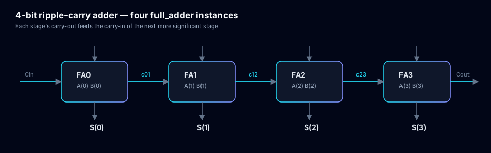
Conceptual signal propagation through a four-stage ripple-carry chain and verified decoder outputs.
Use the left and right arrow keys to rotate the scene. A complete text description is provided; no factual claim depends on the visualization alone.
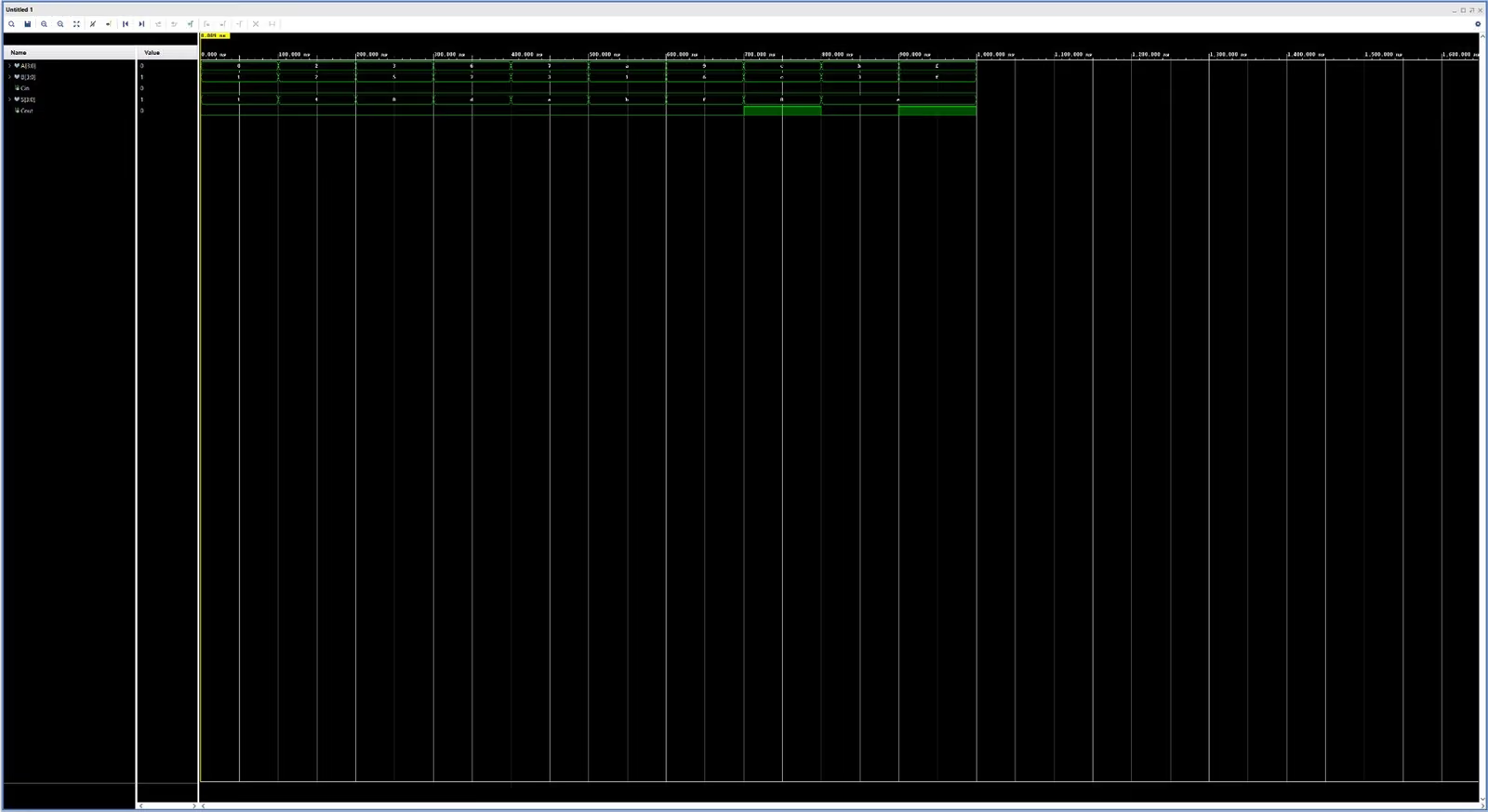
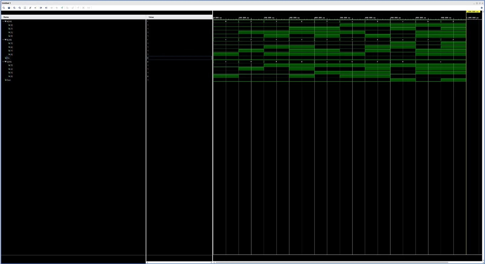
Worked example from the simulation: A equals binary 1011 (eleven), B equals 0110 (six), carry-in zero; the sum is 0001 with carry-out one — seventeen.
Tracing the carry propagation
Four chained full adders from least to most significant bit; each stage's carry-out feeds the next stage.
-
Inputs: A0=1, B0=0, carry-in C0=0. Outputs: S0=1, carry-out C1=0. The exhaustive simulation checked this stage across all 512 input combinations.
-
Inputs: A1=1, B1=1, carry-in C1=0. Outputs: S1=0, carry-out C2=1. The exhaustive simulation checked this stage across all 512 input combinations.
-
Inputs: A2=0, B2=1, carry-in C2=1. Outputs: S2=0, carry-out C3=1. The exhaustive simulation checked this stage across all 512 input combinations.
-
Inputs: A3=1, B3=0, carry-in C3=1. Outputs: S3=0, carry-out C4=1. The exhaustive simulation checked this stage across all 512 input combinations.
Select a stage to inspect it
The point
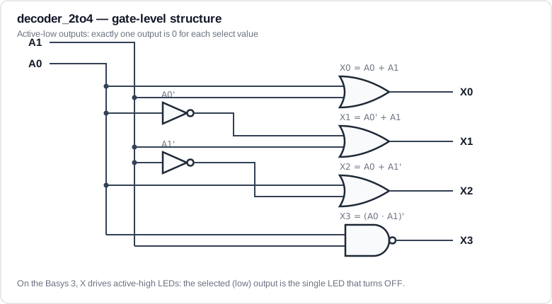
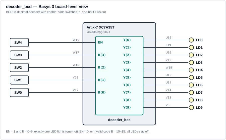
Classroom digital logic usually ends at a waveform screenshot. These two repositories take the same material to open-source standard: every design carries self-checking testbenches that sweep the entire input space — 512 combinations for the 4-bit ripple-carry adder, 36 vectors across the two decoders — plus constraints files mapping to real Basys 3 switches, LEDs, and seven-segment digits.
Verification, stated exactly
The adder’s testbenches replay the lab’s recorded vectors and the full exhaustive sweep under GHDL in CI on every push (no Vivado license needed); the repo includes genuine Vivado behavioral-simulation waveform captures. The full adder was synthesized, implemented, and programmed onto a Basys 3 with all eight truth-table rows checked on switches and LEDs — that on-board step is author-attested; board photos are on the capture list.
Current status
Both repositories run their full testbench suites in GitHub Actions on every push (green as of July 2026). Both are companion work to Logic Design I — labeled as coursework-extended, because that’s what it is.