EMB-03 Team project
Smart-home appliance controller
An Arduino climate/appliance controller with sensor-driven fan control, a four-mode state machine, and an over-temperature safety cutoff — built as a two-person university team.
Recruiter summary
- Problem
- Exercise the core embedded-systems toolkit — ADC sampling, PWM actuation, debounced GPIO, a single-wire sensor protocol, UART logging — as one coherent appliance controller on real hardware.
- Contribution
- A two-person team project with Paola Dorado Galicia: both of us are credited for design, firmware, and testing; I maintain the repository, documentation, and schematics.
- Result
- A working four-mode controller with a 35 °C safety cutoff, eight documented build states, a schematic in three formats, and a candid limitations list.
SENSE-CONTROL
Interactive visualization · drag to inspect
3D ENGINEERING VIEW
The system as an interactive composition
Evidence-based controller composition: sensors, Arduino state machine, LCD, PWM fan, and safety override.
Use the left and right arrow keys to rotate the scene. A complete text description is provided; no factual claim depends on the visualization alone.
The four-mode state machine
State diagram: power-on starts in AUTO; button 1 cycles AUTO, MANUAL, SLEEP; ALARM overrides any mode at 35 degrees and releases when the temperature falls.
-
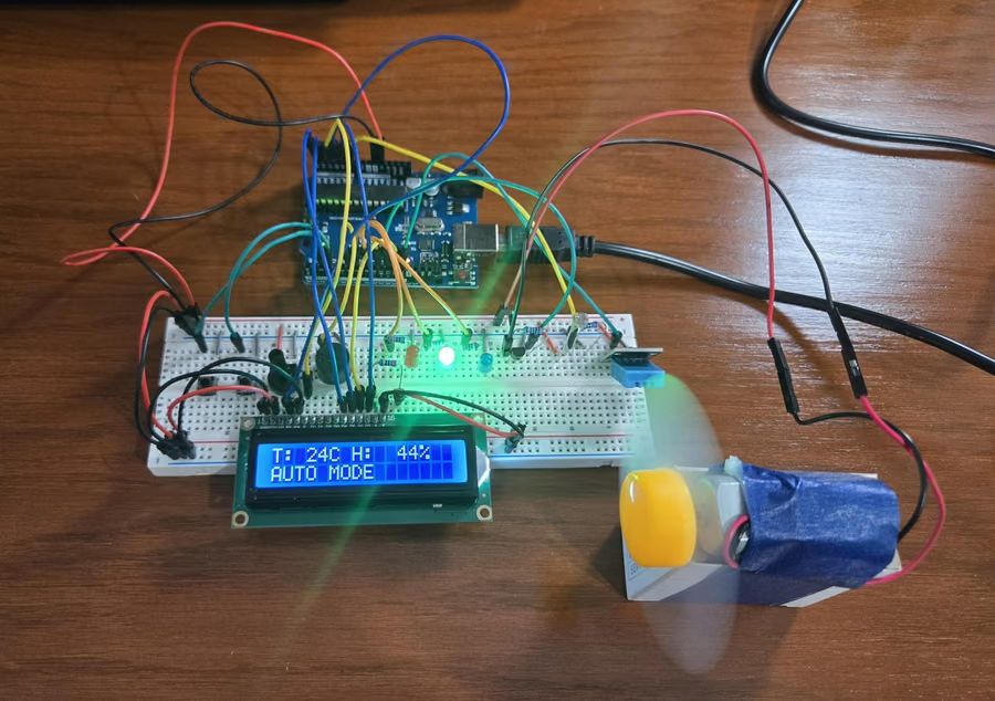
The power-on mode. The DHT11 reading maps to a PWM fan curve: off below 24 °C, then low and medium bands, full from 28 °C.
-
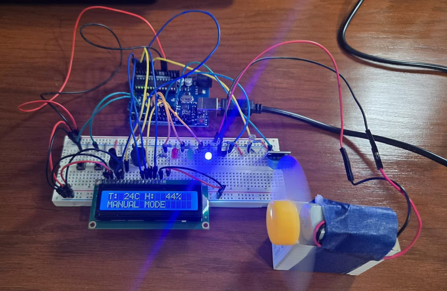
Button 1 moves from AUTO to MANUAL; button 2 cycles the fan OFF → LOW → MEDIUM → FULL.
-
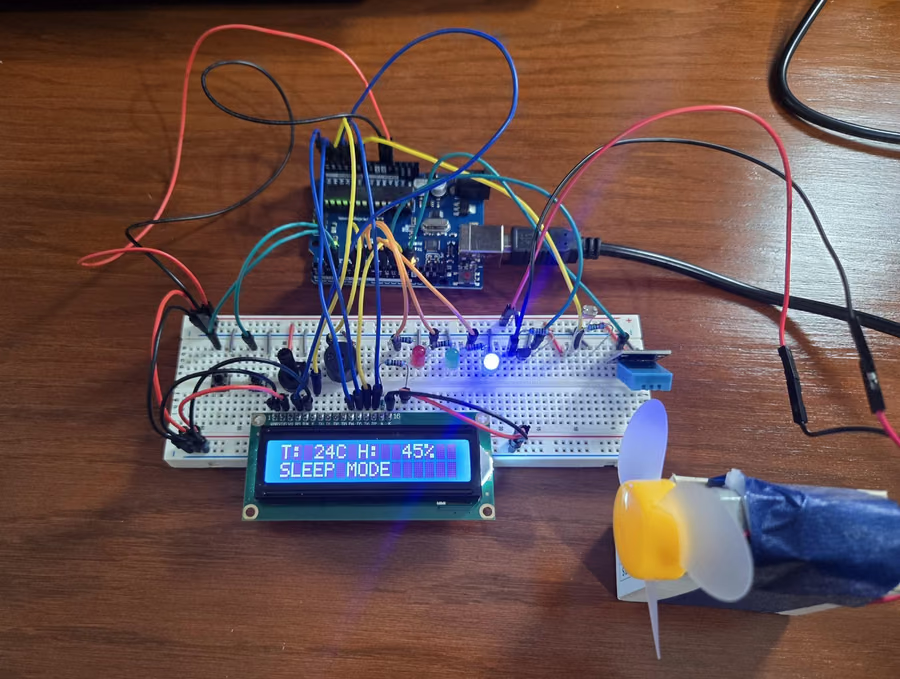
Fan off; the blue LED becomes an adaptive nightlight driven by the LDR reading.
-
At ≥ 35 °C the alarm overrides any mode: the fan is cut, the buzzer sounds, and the red LED stays lit until the temperature falls.
Select a stage to inspect it
What it does
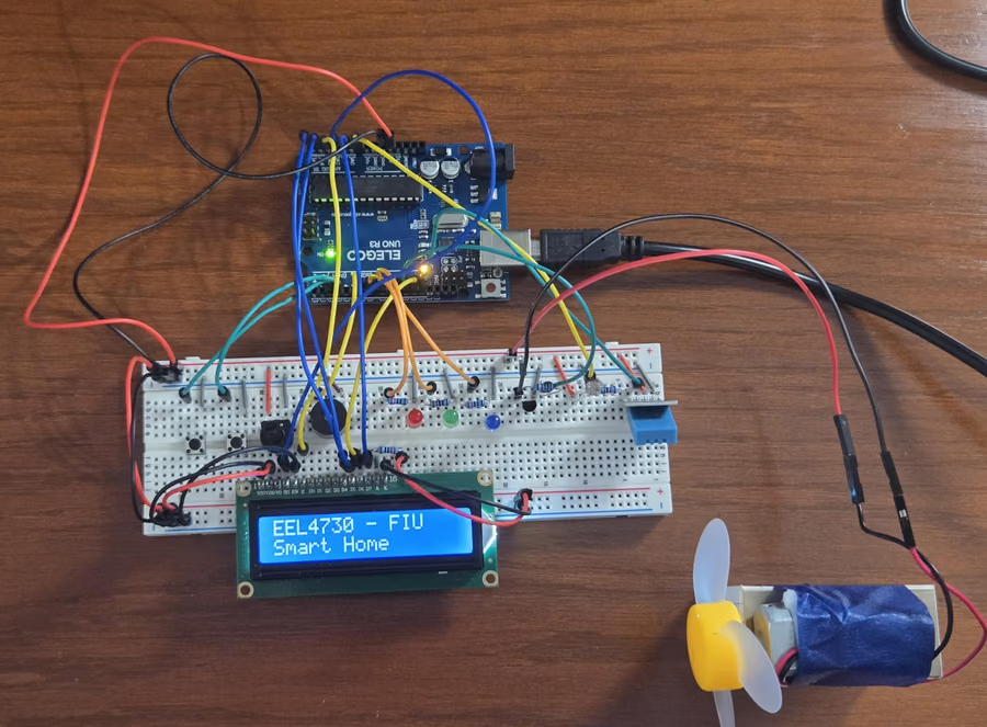
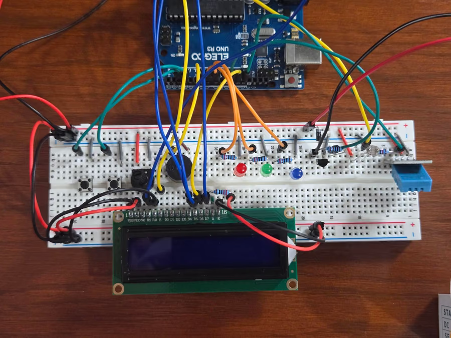
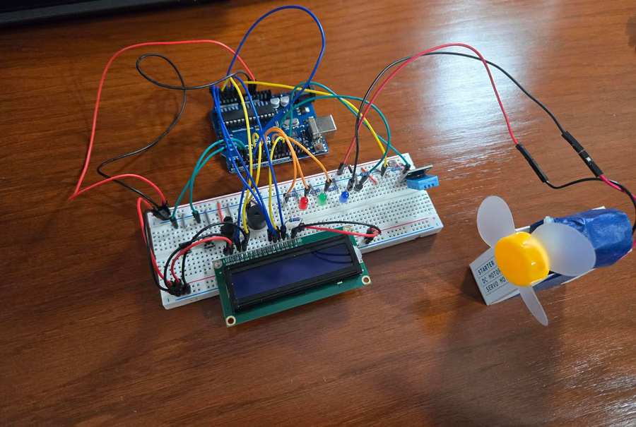
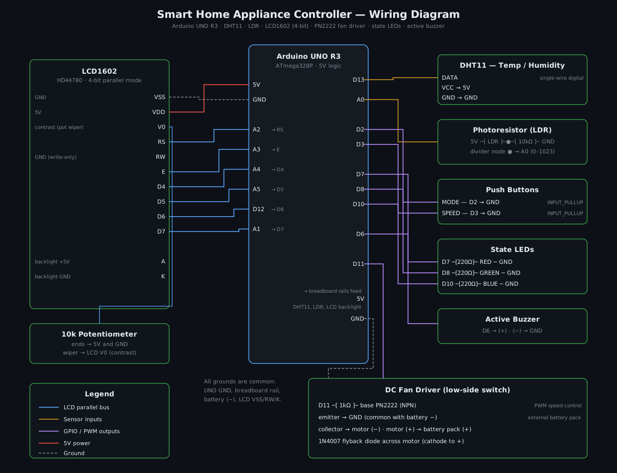
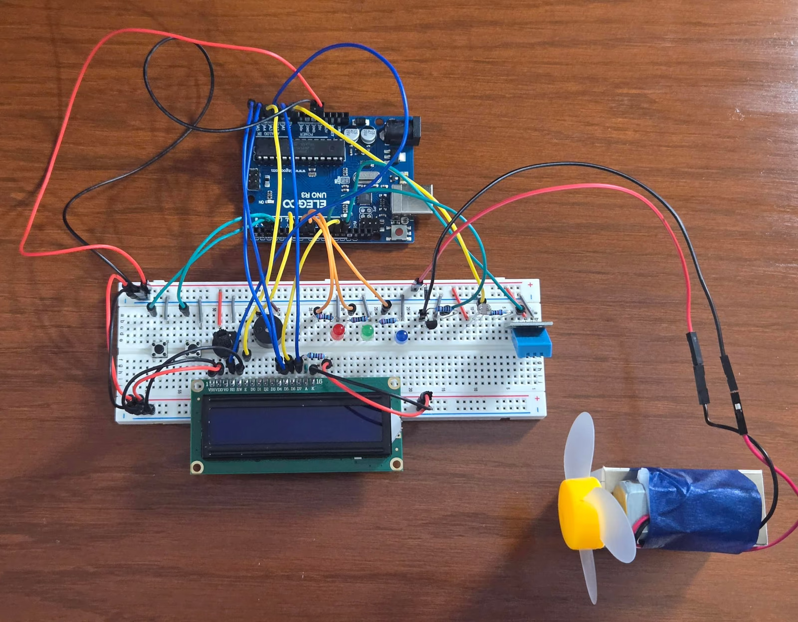
DHT11 temperature/humidity and an LDR light divider feed a four-mode state machine (AUTO / MANUAL / SLEEP / ALARM). AUTO maps temperature bands to fan speed through a PN2222 low-side PWM driver with a flyback diode; at 35 °C an ALARM override cuts the fan and sounds the buzzer. An LCD1602 shows state; everything logs over UART.
Credit, precisely
This was a team project for EEL 4730 (Programming Embedded Systems) at FIU, built with Paola Dorado Galicia. The repository preserves the team’s original commit history — the original firmware commits are hers — and adds my later documentation, reorganization, and schematics on top. Both of us are credited for design, firmware, and testing, as the project was actually done.
Why it’s here
It demonstrates the unglamorous fundamentals on real hardware: ADC sampling, PWM actuation, debounced GPIO, a single-wire sensor protocol, UART logging, and a state machine — with eight build photos across its modes, a schematic in three formats, and a video walkthrough. The README’s limitations section is candid: a blocking main loop that can miss button presses, coarse ±2 °C sensor resolution, compile-time thresholds, uncalibrated LDR values.